This is the last of a series of three blogs examining methods of tolerancing plastic moulded parts using various International Standards and Tolcap.
In previous blogs I described how you can use Tolcap rather than
DIN 16901,
DIN 16742 or ISO 20457 to find capable tolerances for your plastic moulded parts.
We learned how to get to the appropriate Tolcap map,
but it is clear if we plot capability curves for plastic mouldings with and without a geometric issue:
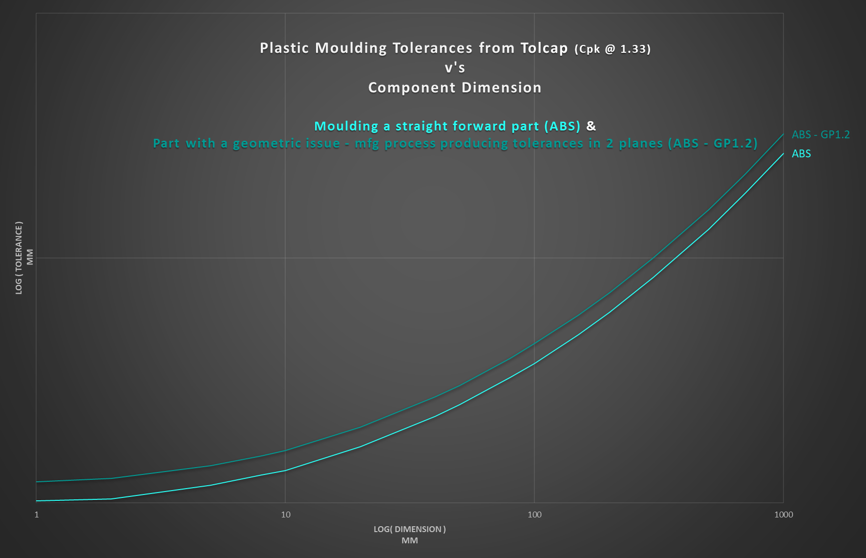 Tolcap capability curve, Cpk = 1.33, tolerances for ABS moulded part with geometric issue (ABS GP 1.2), and without a geometric issue (ABS)
that geometry and process issues can require that the tolerance from the map be significantly increased to achieve process capability.
So let’s go through what might concern us as we apply the Tolcap Gp and Vp Wizards.
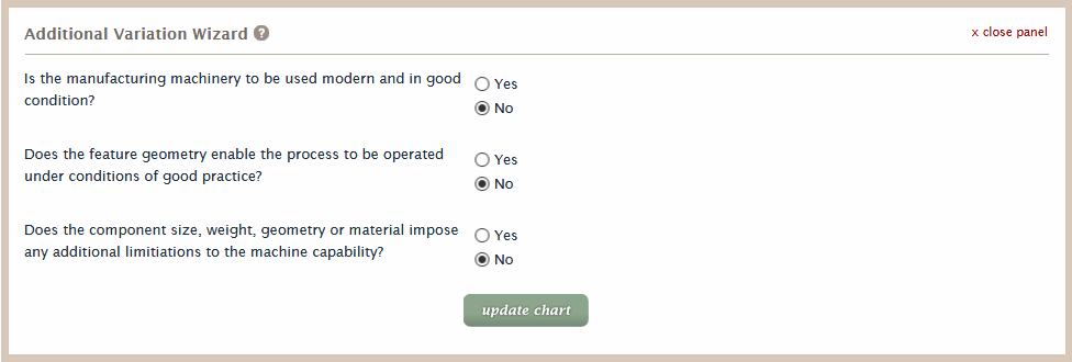
Tolcap Additional Variation, Vp, Wizard
The order we apply the wizards does not matter, so let’s look at Vp first.
 Tolcap Additional Variation, Vp, Wizard
Considering each of the Additional Variation questions:
-
Is the manufacturing machinery to be used modern and in good condition?
Modern injection moulding machines will enable close control of times and temperatures
and permit adequately fine control of pressures through the injection and hold phases.
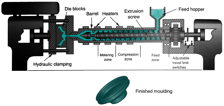 Injection Moulder (Ref 2)
-
Does the feature geometry enable the process to be operated under conditions of good practice?
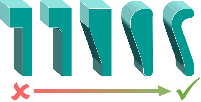 Progressive part redesign to avoid sharp corners / change wall thickness gradually / core out thick sections
The geometry of moulded parts and its effects on how the material may be injected and flow round the mould is crucial.
There are internet guides and videos, many published by
CAE
vendors who offer packages to address many of these issues.
Some important points are:
Progressive part redesign to avoid sharp corners / change wall thickness gradually / core out thick sections
The geometry of moulded parts and its effects on how the material may be injected and flow round the mould is crucial.
There are internet guides and videos, many published by
CAE
vendors who offer packages to address many of these issues.
Some important points are:
-
Injection moulded parts should ideally have wall thickness
< 5mm (0.2") and > 0.5mm (0.02")
- with 0.25mm (0.01") as a minimum limit.
It follows that solid parts should be cored out.
-
 Part redesigned to equalise wall thicknesses and avoid sharp corners.
Avoid large variations and abrupt changes in wall thicknesses.
Part redesigned to equalise wall thicknesses and avoid sharp corners.
Avoid large variations and abrupt changes in wall thicknesses.
In addition to simplifying the flow pattern, this will help reduce variations in shrinkage that can lead to warping,
and avoid creating stress concentration areas that may reduce a part’s impact strength.
- Where wall thickness changes there should be transition zones again to reduce the possibility of stress concentrations,
as well as warping, sinks or voids.
- Any sharp corners, external or internal at the base of bosses and ribs for example should be avoided.
Outside radii should be at least 150% of the wall thickness, internal radii 50%, though less for bosses
- 25% to avoid sink problems.
-
Does the component size, weight, geometry or material impose any additional limitations to the
machine capability?
Plastic components may come in a wide range of sizes anything between 10g and 25kg,
but it is important that the capacity of the moulding machine is adequate.
Note that the clamping force required to keep the mould closed is proportional to the footprint area of the components in the mould.
Such design guidelines should be considered when applying the Vp Wizard.
Tolcap Geometric Variation, Gp, Wizard
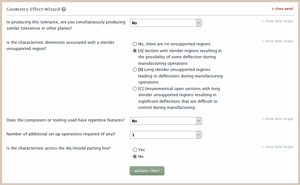 Tolcap Geometry Effect, Gp, Wizard
Considering each of the Geometric Variation questions:
- In producing this tolerance, are you simultaneously producing similar tolerances in other planes?
Of course plastic mouldings have dimensions in different planes,
but check whether these are in the same area and may conflict: do you need a rib with an important length and also thickness?
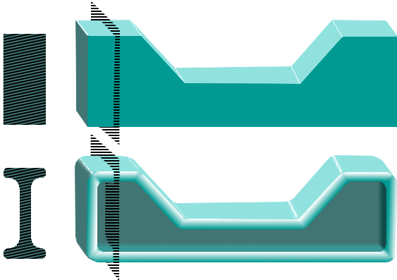
- Is the characteristic dimension associated with a slender unsupported region?
Slender unsupported sections are a real problem in plastic moulding because they may droop or warp when the part is ejected from the mould and still cooling.
You can pay more to prolong the hold time in the mould or for a cooling jig, but can you design some support into the moulding - even something to snap off later?
- Number of additional set-up operations required (if any)?
Additional set ups can take account of parts made by a sequence of processes.
Overmoulding may demand some concession when setting tolerances.
- Is the characteristic across the die/mould parting line?
...and of course all standards and Tolcap recognise the difference between dimensions within the mould and across a parting line.
In conclusion
We hope these blogs have:
- shown how Tolcap lines up with the various standards for setting tolerances for plastic mouldings
- explained how you can use Tolcap to arrive at process capable tolerances for your design
- shown that Tolcap can adjust tolerance suggestions to allow for real world issues such as part geometry and process limitations.
References
Written by:

Richard Batchelor MA, MBA, CEng, FIEE
Richard is a founding member of the Capra Technology team.
Thanks to Ian Maynard CEng MIMechE for his support in writing this blog
(www.IanMaynardCEng.com).
Related blogs
‘The Tolcap Rough Guide to Tolerancing Plastic Mouldings’ series (Dec 2019):